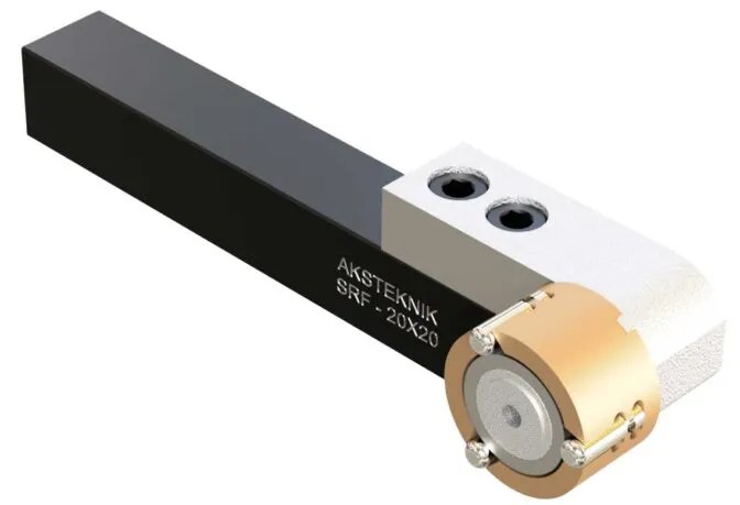
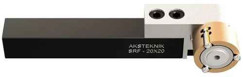
Single Roll Burnishing Tool
Spring-loaded single roller for external surface finishing — cylindrical, conical, face and contour surfaces. Ra 0.034 µm demonstrated. Simple, economical and easy to use on any lathe.
- Surface finish: Ra < 0.1 µm — Ra 0.034 µm demonstrated
- Works on all metal types below 40–45 HRC
- Patented flexible spring head — protects lathe from rigid loads
- Cylindrical, conical, face, fillet and contour surfaces
- Left-hand and right-hand operation
- 20×20 mm and 25×25 mm square shanks
Overview
Single Roll Burnishing — Versatile External Surface Finishing
The SRF uses a single hardened roller mounted on a patented flexible spring head. As the workpiece rotates on the lathe, the roller presses against the surface with controlled force — roughness peaks are plastically deformed into valleys, producing a mirror-like finish.
Unlike multi-roller tools that surround a bore or shaft, the single roll design contacts the surface from one side. This makes it far more versatile — it can finish cylindrical surfaces, conical tapers, face surfaces, fillets, radii and complex contours that multi-roller tools cannot reach.
The burnishing force is transferred from the machine to the workpiece through the flexible spring head, which prevents rigid contact. This protects the lathe bearings and ways while maintaining consistent contact force despite minor surface variations.
- Ra 0.034 µm demonstrated — mirror finish on all metals
- Cylindrical, conical, face, fillet and contour surfaces
- Patented flexible spring head — protects lathe from shock loads
- Left-hand and right-hand operation — reverse rolling head
- No chips, no dust — clean, quiet process
- CNC and universal lathes — mount in any tool post
Video
SRF Single Roll Burnishing Tool in Action — Ra 0.034 µm
Watch the SRF single roll burnishing tool in operation on a CNC lathe — the video shows the tool working on the workpiece, the finished part and Ra 0.034 µm surface roughness measurement verified with a surface roughness tester.
Tool Design
SRF Tool Components & Dimensions
The SRF consists of 8 precision components assembled into a compact, maintenance-free unit.
Tool Components
- Cage — houses the roller and taper assembly
- Roller — hardened contact roller, Ø 16 mm
- Taper — conical element for roller positioning
- Bearing — center bearing for smooth rotation
- Bushing — supports the bearing assembly
- Pin — secures internal components
- Spring Head — patented flexible mechanism for force control
- Shank — 20×20 or 25×25 mm square for tool post mounting
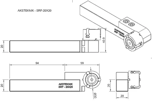
Key Dimensions (SRF-20X20)
| Parameter | Value |
|---|---|
| Total length | 94 mm |
| Shank size | 20 × 20 mm |
| Cage diameter | Ø 30 mm |
| Total width (with roller) | 41 mm |
| Roller diameter | Ø 16 mm |
Specifications
SRF Technical Specifications
| Parameter | Value |
|---|---|
| Achievable surface finish | Ra < 0.1 µm (Ra 0.034 µm demonstrated) |
| Compatible materials | All plastically deformable metals (steel, stainless, aluminium, copper, brass, bronze, cast iron) |
| Max workpiece hardness | 40–45 HRC |
| Force control | Patented flexible spring head |
| Max burnishing pressure | 1 mm on X-axis (2 mm on diameter) |
| Recommended starting pressure | 0.4 mm on X-axis (0.8 mm on diameter) |
| Pre-machining roughness | 5–20 µm (Rz or Rt) |
| Operation direction | Left-hand and right-hand (reversible rolling head) |
| Application surfaces | Cylindrical, conical, face, fillet, radius, contour |
| Tool alignment tolerance | 90° ±0.05° (check with dial indicator) |
| Burnishing angle | 1.0–1.5° |
| Coolant | Standard machine coolant fluid |
Feeds & Speeds
Single Roll Burnishing — Feeds & Speeds by Material
Calculate spindle speed from surface speed: RPM = Vc × 1000 / (Ø × 3.14). Example: Ø 50 mm workpiece at Vc 50 m/min → RPM = 50×1000 / (50×3.14) = 318 rpm.
| Material | Surface Speed (m/min) | Feed (mm/rev) |
|---|---|---|
| Steel | 50–150 | 0.05–0.5 |
| Stainless Steel | 50–150 | |
| Cast Iron | 50–150 | |
| Aluminium | 50–200 | |
| Copper & Alloys | 50–200 |
Pre-Machining Feed Formula
To achieve the recommended 5–20 µm (Rz) pre-machining roughness:
Feed per revolution = Tool nose radius / 2
Example: 0.2 mm/rev feed with an R0.4 mm cutting tool nose radius.
Setup Guide
SRF Setup & Operation Guide
- 1
Mount & Align
Clamp the SRF square shank in your lathe tool post. Align the tool so the roller contacts the workpiece at 90° ±0.05°. Use a dial indicator over a 100 mm span to verify alignment. Set the burnishing angle to 1.0–1.5°.
- 2
Set Tool Offset
Use a workpiece with a known exact diameter. Rotate at low speed (e.g. 100 RPM). Slowly move the tool in X direction until the roller lightly touches the surface. Continue pressing until the center bearing begins to rotate — this is the exact pressure point. Set this diameter as your X-axis tool offset.
- 3
Pre-Machine the Surface
Turn the workpiece to near-final dimensions. Pre-machined surface roughness should be 5–20 µm (Rz or Rt). Use feed per revolution = tool nose radius / 2. Leave a small stock allowance — perform a test run to determine the actual material removal for your setup.
- 4
Set Burnishing Pressure
Start with 0.4 mm additional pressure on the X-axis (0.8 mm on diameter). Gradually increase based on material yield strength. Never exceed 1 mm on X-axis (2 mm on diameter) — excessive pressure causes rigid contact that can damage the tool, workpiece or machine.
- 5
Burnish
Always start 2–3 mm inside the surface to be burnished — approach from the correct direction (along the Z-axis, not perpendicular). Apply the roller with the specified force and feed along the workpiece at 0.05–0.5 mm/rev. Use clean coolant. Ensure the roller surface is free of chips and contaminants before starting.
Operation Direction
The SRF tool is suitable for both left-hand and right-hand operations. Simply reverse the rolling head to match the required operation direction. No additional parts needed.
Troubleshooting
Single Roll Burnishing — Troubleshooting
Desired surface quality not achieved
Causes: Burnishing force too low, pre-machined surface too rough or uneven, tool misaligned.
Solution: Increase burnishing force. Improve pre-machining surface quality. Verify tool is mounted at 90° ±0.05° with a dial indicator.
Flaking or cracking surface
Causes: Burnishing force too high, feed rate too high.
Solution: Reduce burnishing force. Decrease feed rate.
Repeating marks or patterns
Causes: Taper rollers worn, chips stuck on roller, coolant dirty.
Solution: Replace taper roller. Clean roller surface thoroughly. Replace coolant — a 5–10 µm filtration system is recommended.
Wavy surface
Causes: Burnishing force too high, feed rate too high, poor pre-machined surface.
Solution: Reduce burnishing force. Lower feed rate. Inspect and correct pre-machined surface.
Tool or workpiece overheating
Causes: Burnishing force too high, insufficient coolant, tool and workpiece axes misaligned, incorrect mounting.
Solution: Reduce burnishing force. Increase coolant flow. Check alignment at 90° ±0.05° with dial indicator.
Dull or matte surface finish
Causes: Coolant too thick or viscous.
Solution: Dilute or replace the coolant fluid.
Surface mark at tool entry point
Causes: Contact distance between tool and workpiece at entry is too short.
Solution: Increase the initial contact distance — always start 2–3 mm inside the surface.
Applications
Single Roll Burnishing Applications & Surface Geometries
The single roll design makes the SRF suitable for a wide range of external surface geometries that multi-roller tools cannot address.
- Cylindrical surfaces — shafts, pins, journals, bearing surfaces
- Conical surfaces — tapers, transition zones
- Face surfaces — end faces, shoulders, flanges
- Fillets & radii — stress-relief radii, grooves
- Contoured surfaces — complex profiles on turned parts
- Seal surfaces — O-ring grooves, grease seal areas
Suitable Industries
The SRF is used wherever external surfaces on turned parts require a mirror finish, improved wear resistance or tighter tolerances — including automotive, hydraulics, pneumatics, medical devices and general precision engineering.
Ordering
Order Codes
| Order Code | Roller Ø | Shank | Description |
|---|---|---|---|
| SRF-20X20 | Ø 16 mm | 20 × 20 mm | Single roll burnishing tool, square shank for CNC and universal lathes |
| SRF-25X25 | Ø 16 mm | 25 × 25 mm | Single roll burnishing tool, square shank for CNC and universal lathes |
Larger roller diameters (e.g. SRF35) available on request. Contact us for custom configurations.
FAQ
Frequently Asked Questions
-
What is single roll burnishing?
Single roll burnishing uses one hardened roller on a spring-loaded arm to press against a rotating workpiece surface. Unlike multi-roller tools that surround a bore or shaft, a single roll tool contacts the surface from one side — making it versatile enough for cylindrical, conical, face, fillet and contoured surfaces. The patented flexible spring head provides consistent force while protecting the lathe from rigid shock loads.
-
What surface finish can the SRF achieve?
The SRF achieves Ra below 0.1 µm on all plastically deformable metals — Ra 0.034 µm has been demonstrated on steel. The result depends on the pre-machined surface quality (5–20 µm Rz ideal), material type and parameters (speed, feed, force).
-
When should I use a single roll tool instead of a multi-roller tool?
Use a single roll tool when the workpiece geometry is not a simple straight bore or shaft. Single roll tools excel on external cylindrical surfaces, conical tapers, face (end) surfaces, fillets, radii and complex contours. Multi-roller tools are better when you need maximum concentricity and precision on straight bores or shafts.
-
What machines is the SRF compatible with?
The SRF fits any CNC lathe or universal lathe with a standard tool post. It is available with 20×20 mm and 25×25 mm square shanks — the most common tool post sizes. No machine modification is required.
-
What materials can be burnished with the SRF?
The SRF works on all plastically deformable metals: steel, stainless steel, aluminium, copper, brass, bronze and cast iron. Workpiece hardness should be below 40–45 HRC.
-
Can the SRF be used for both left-hand and right-hand operations?
Yes. Simply reverse the rolling head to match the required operation direction. The tool is suitable for both left-hand and right-hand operations without any additional parts.
-
How do I determine the correct burnishing pressure?
Start with 0.4 mm additional pressure on the X-axis (0.8 mm on diameter). Gradually increase based on the material's yield strength, but never exceed 1 mm on the X-axis (2 mm on diameter). Excessive pressure causes rigid contact that can damage the tool, workpiece or machine.
-
Are larger single roll models available?
Currently the SRF with Ø 16 mm roller is the standard production model. Larger models (e.g. SRF35) can be manufactured on request for applications requiring a bigger roller contact area. Contact us to discuss your requirements.
Related Products
Other Burnishing Tools
Need help selecting the right burnishing tool for your application?
Our engineers will recommend the correct tool type, size and parameters for your workpiece geometry and material.
Contact Us