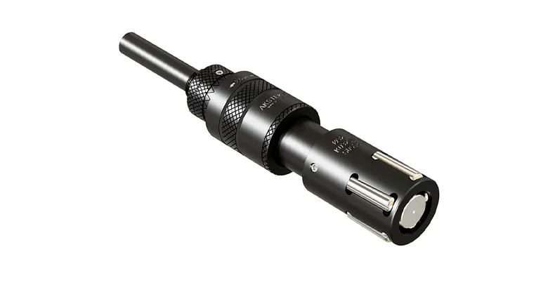
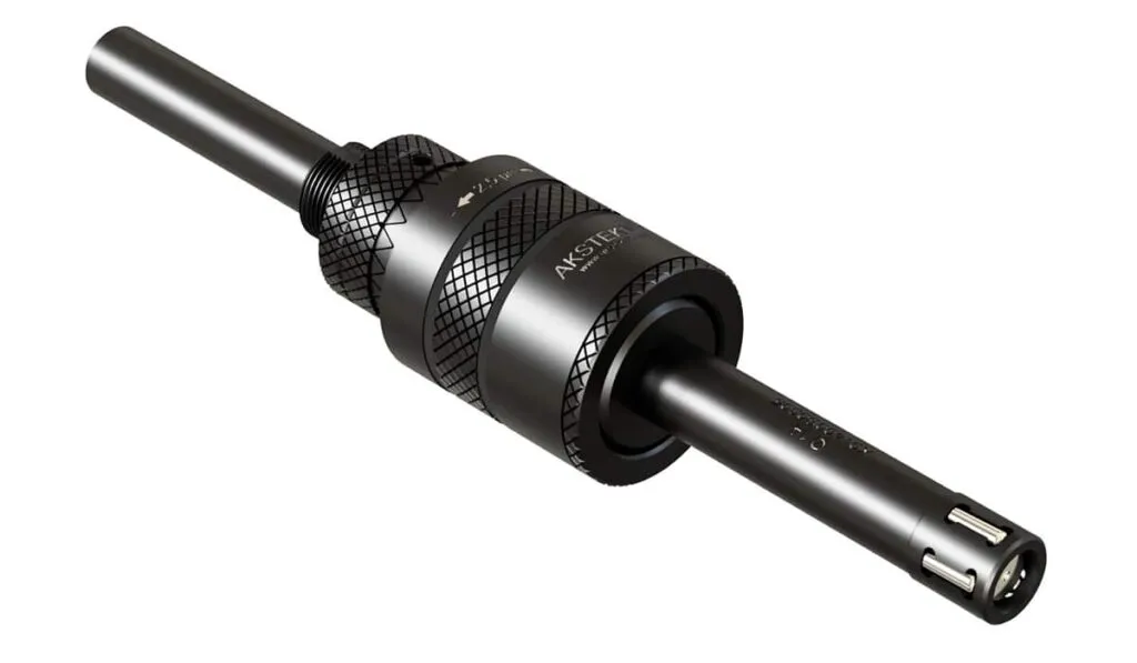
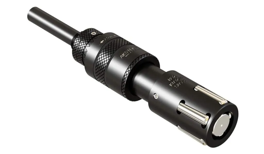
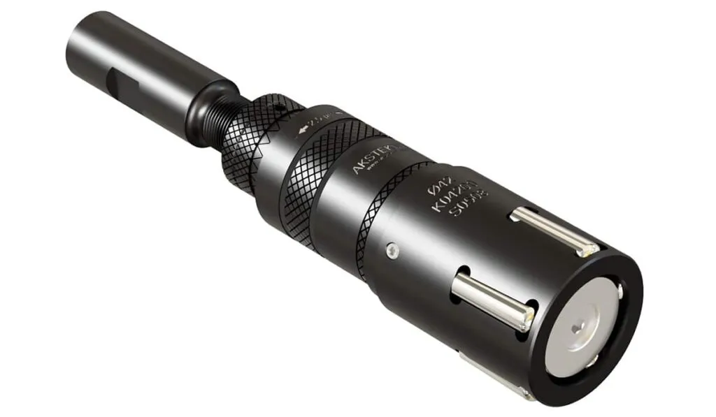
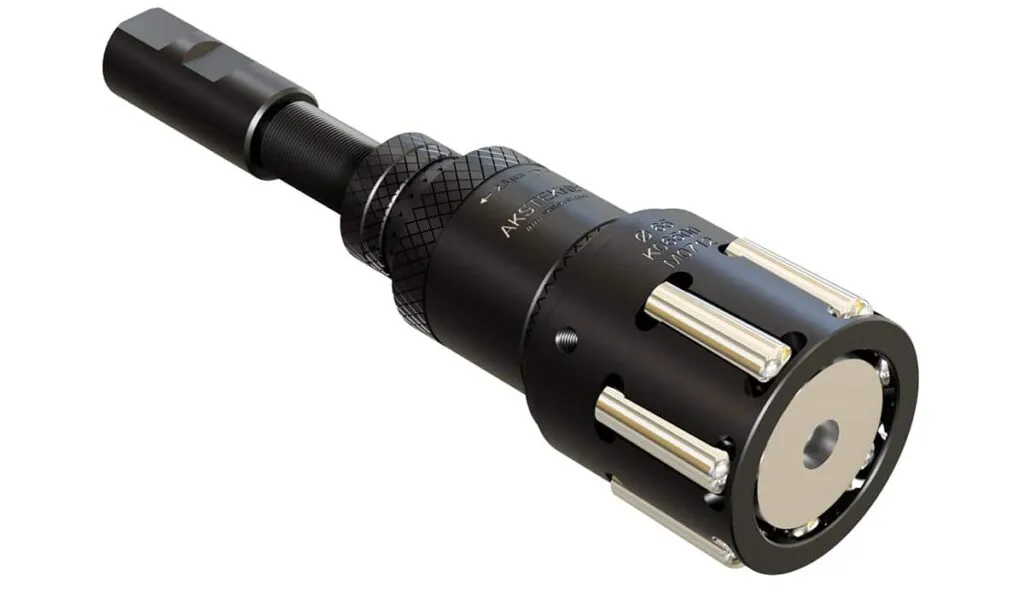
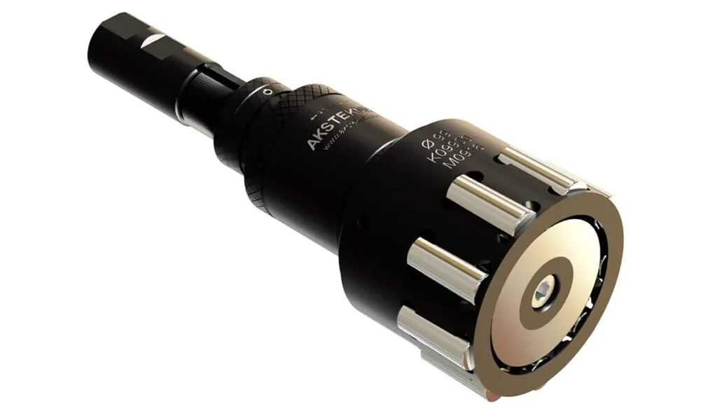
Internal Roller Burnishing Tools
Multi-roller tools for through holes, blind holes and stepped bores — diameter range 9 to 160 mm. Mirror-finish surfaces (Rz < 1 µm) in a single pass, with 2.5 µm adjustment precision.
- Diameter range: Ø 9–160 mm (0.5 mm increments)
- Surface finish: Rz < 1 µm in seconds
- Adjustment precision: 2.5 µm per graduation
- Through hole, blind hole and self-feeding variants
- Weldon (12, 20, 25, 32 mm) and Morse (MT2–MT5) shanks
Overview
Internal Bore Finishing in Seconds
Burnishing is the process of compressing the surface roughness using rollers, resulting in mirror-like surfaces. It is performed after pre-processing operations such as turning and reaming.
With internal hole tools, diameter adjustments can be made with a precision of 2.5 microns (0.0025 mm). The process duration is very short — typically lasting only a few seconds.
When no heat treatment is applied, burnishing produces excellent results on all types of metals: aluminium, cast iron, steel, stainless steel, bronze and more.
- Rz < 1 µm smooth surfaces achievable
- Desired dimensions easily and quickly obtained
- Single-pass process — seconds, not minutes
- Polishes and hardens the surface simultaneously
- No chips, no dust, no noise — environmentally friendly
- Compatible with all universal and CNC machines
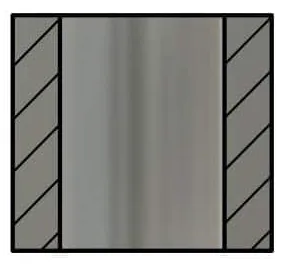
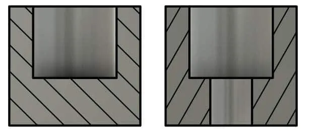
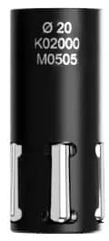
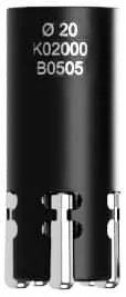
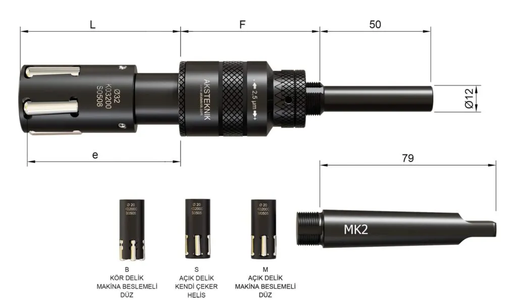
Tool Types
Through Hole & Blind Hole Configurations
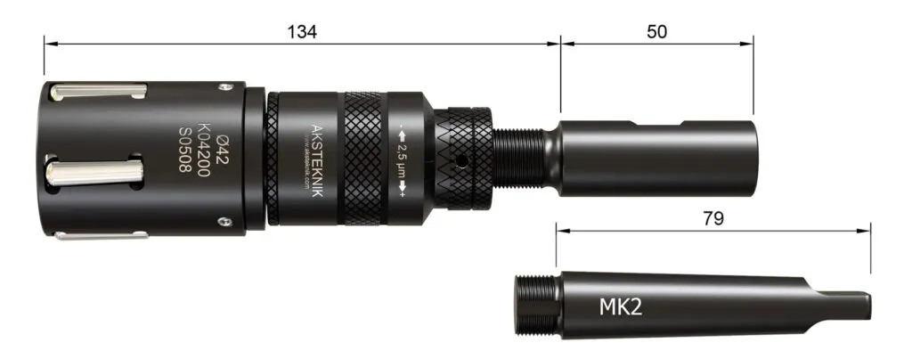
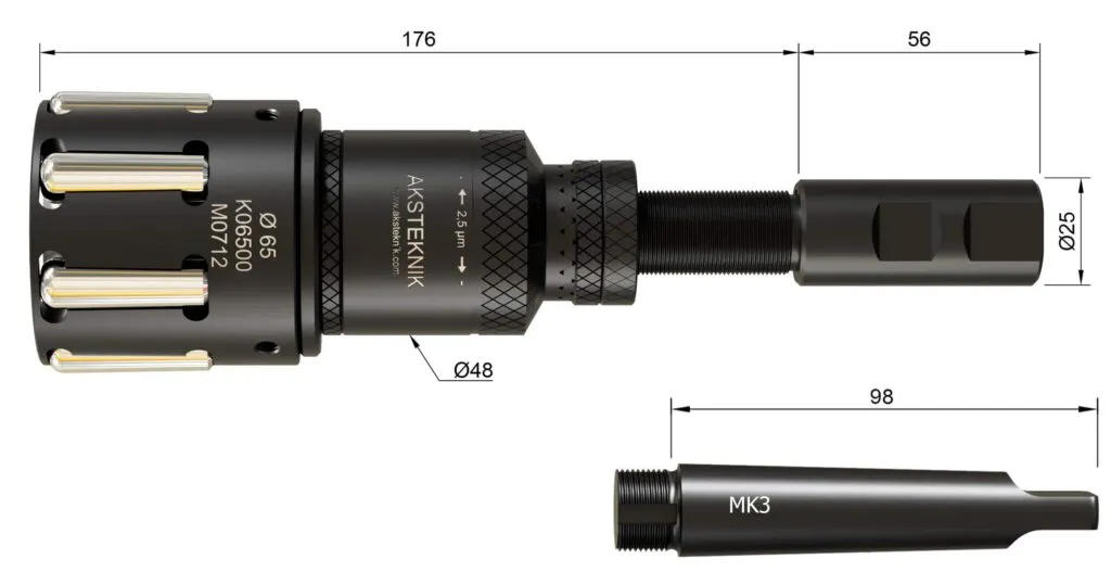
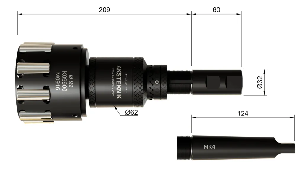
Specifications
Internal Burnishing Tool Specifications
Ø 9 mm – Ø 18.5 mm
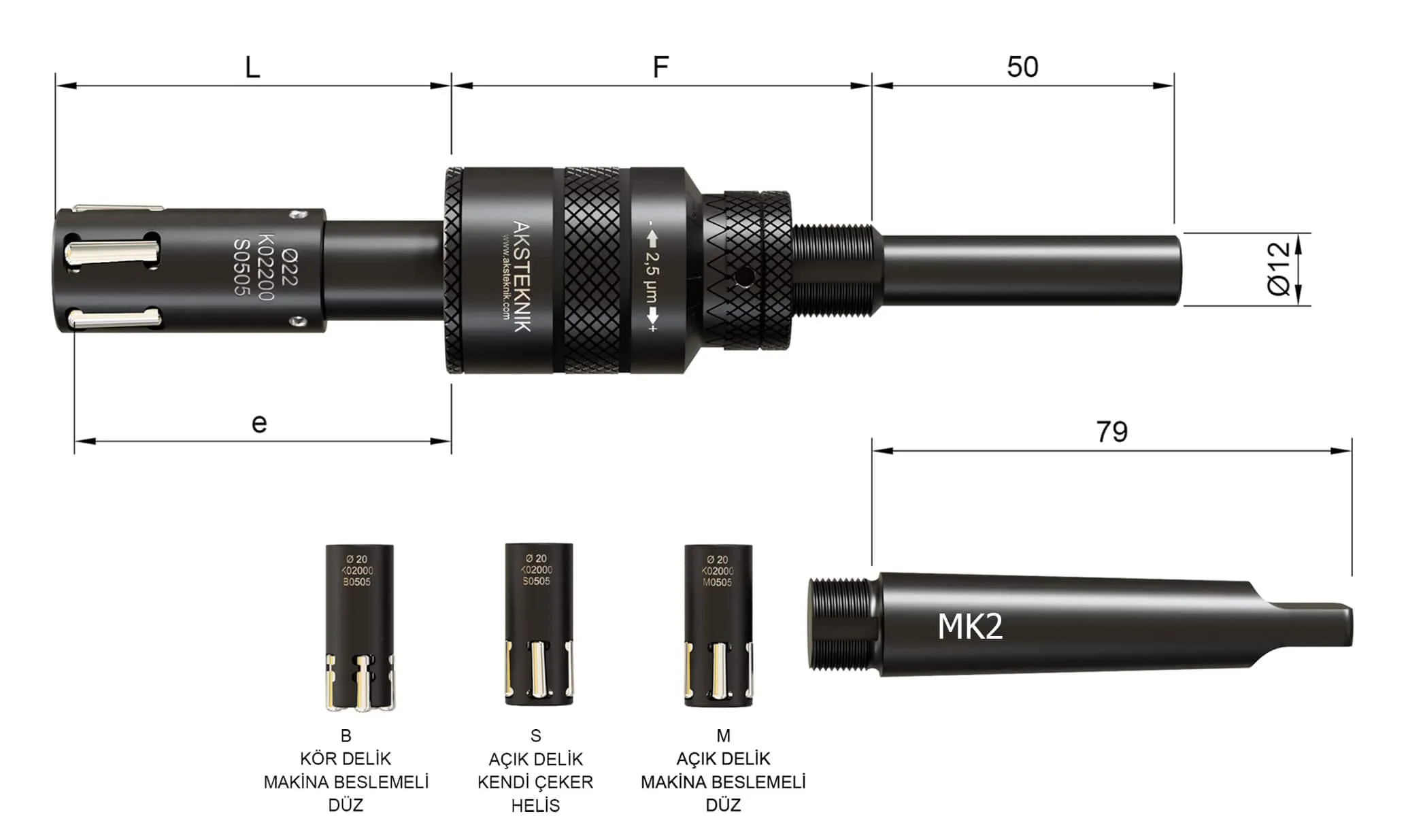
| Dia Ø | Adjustment Range | Dimensions | Rollers | ||||||
|---|---|---|---|---|---|---|---|---|---|
| Through Hole | Blind Hole | Working Length | Through Hole | Blind Hole | |||||
| M/S | B | e | L | F | Code | Number of Rollers | Code | Number of Rollers | |
| 9–9.5 | -0.10 +0.30 | -0.00 +0.15 | 60 | 66 | 70 | BM02 | 4 | BB02 | 4 |
| 10–10.5 | -0.10 +0.30 | -0.00 +0.15 | 60 | 66 | 70 | BM03 | 4 | BB03 | 4 |
| 11–16.5 | -0.10 +0.30 | -0.00 +0.15 | 60 | 66 | 70 | BM03 | 5 | BB03 | 5 |
| 17–18.5 | -0.10 +0.30 | -0.00 +0.15 | 60 | 66 | 70 | BM05 | 5 | BB05 | 5 |
Ø 19 mm – Ø 25 mm
| Dia Ø | Adjustment Range | Dimensions | Rollers | ||||||
|---|---|---|---|---|---|---|---|---|---|
| Through Hole | Blind Hole | Working Length | Through Hole | Blind Hole | |||||
| M/S | B | e | L | F | Code | Number of Rollers | Code | Number of Rollers | |
| 19–25 | -0.10 +0.40 | -0.00 +0.25 | 60 | 66 | 70 | BM05 | 5 | BB05 | 5 |
Ø 25 mm – Ø 35 mm
| Dia Ø | Adjustment Range | Dimensions | Rollers | ||||||
|---|---|---|---|---|---|---|---|---|---|
| Through Hole | Blind Hole | Working Length | Through Hole | Blind Hole | |||||
| M/S | B | e | L | F | Code | Number of Rollers | Code | Number of Rollers | |
| 25–28 | -0.10 +0.40 | -0.00 +0.25 | 65 | 72 | 67 | BM05 | 5 | BB05 | 5 |
| 28.5–35 | -0.10 +0.40 | -0.00 +0.25 | 65 | 72 | 67 | BM08 | 5 | BB08 | 5 |
Ø 35.5 mm – Ø 49.5 mm
From Ø 35.5 mm onwards, the working length is unlimited — the tool can burnish bores of any depth.
| Dia Ø | Adjustment Range | Working Length | Rollers | ||||
|---|---|---|---|---|---|---|---|
| M/S | B | Code | Number of Rollers | Code | Number of Rollers | ||
| 35.5–49.5 | -0.10 +0.40 | -0.00 +0.25 | ∞ Unlimited | BM08 | 5 | BB08 | 5 |
Ø 50 mm – Ø 85 mm
| Dia Ø | Adjustment Range | Working Length | Rollers | ||||
|---|---|---|---|---|---|---|---|
| M/S | B | Code | Number of Rollers | Code | Number of Rollers | ||
| 50–52 | -0.10 +0.80 | -0.00 +0.25 | ∞ Unlimited | BM12 | 5 | BB12 | 5 |
| 53–70 | -0.10 +0.80 | -0.00 +0.25 | ∞ Unlimited | BM12 | 7 | BB12 | 7 |
| 71–85 | -0.10 +0.80 | -0.00 +0.25 | ∞ Unlimited | BM12 | 9 | BB12 | 9 |
Ø 86 mm – Ø 160 mm
| Dia Ø | Adjustment Range | Working Length | Rollers | ||||
|---|---|---|---|---|---|---|---|
| M/S | B | Code | Number of Rollers | Code | Number of Rollers | ||
| 86–99 | -0.10 +0.80 | -0.00 +0.25 | ∞ Unlimited | BM16 | 9 | BB16 | 9 |
| 100–109 | -0.10 +0.80 | -0.00 +0.25 | ∞ Unlimited | BM16 | 11 | BB16 | 11 |
| 110–121 | -0.10 +0.80 | -0.00 +0.25 | ∞ Unlimited | BM20 | 9 | BB20 | 9 |
| 122–150 | -0.10 +0.80 | -0.00 +0.25 | ∞ Unlimited | BM20 | 11 | BB20 | 11 |
| 151–160 | -0.10 +0.80 | -0.00 +0.25 | ∞ Unlimited | BM20 | 13 | BB20 | 13 |
User Manual
Setup & Adjustment
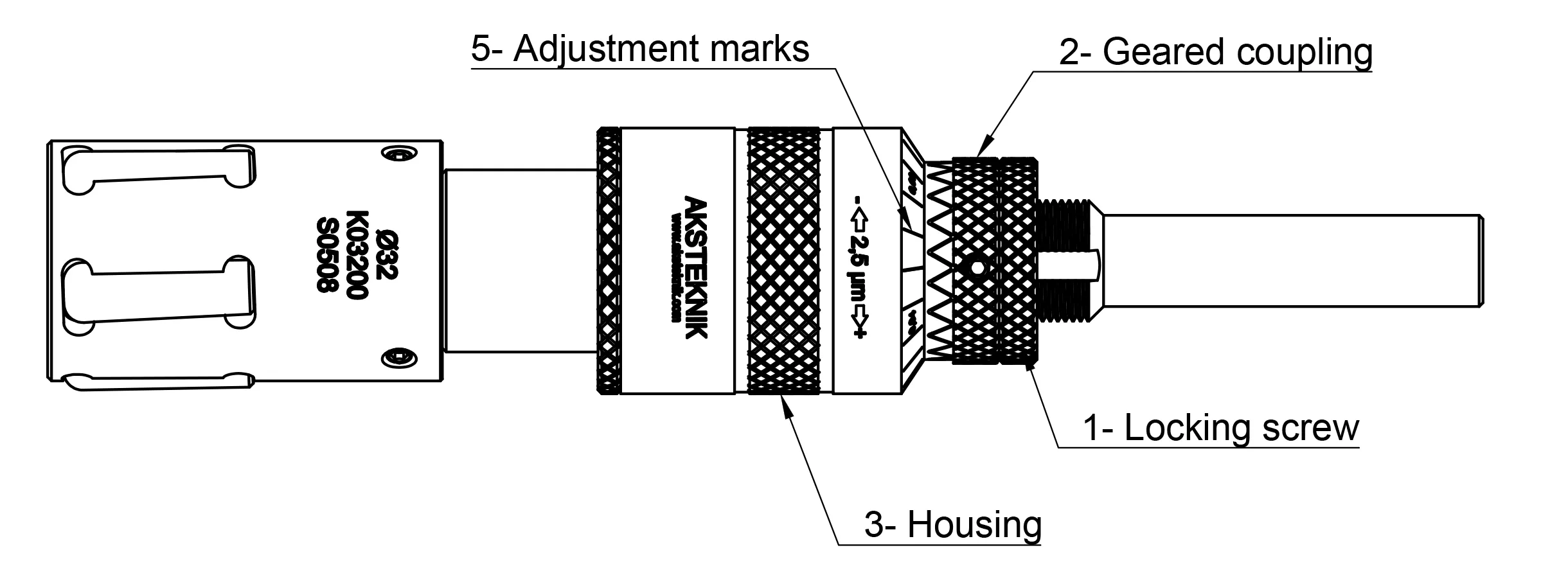
- 1
Release the Locking Screw
Loosen the lock nut to allow housing rotation.
- 2
Pull Back the Geared Fixing Coupling
Disengage the geared coupling so the housing can rotate freely.
- 3
Contract the Tool
Turn the housing right (clockwise) to decrease the diameter so the tool slides smoothly into the bore.
- 4
Expand Until Contact
When the tool slides smoothly, rotate the housing left (counter-clockwise) to expand until the rollers make contact with the bore surface. Then withdraw the tool.
- 5
Set Stock Allowance
Using the graduation marks on the housing (each mark = 2.5 µm = 0.0025 mm), adjust the diameter for the amount of stock left in the bore.
- 6
Test & Fine-Tune
Perform the burnishing pass on a workpiece and check both dimensions and surface finish. Do not burnish the same part more than twice. Always tighten the lock nut after each adjustment.
Tool Holders
Shank Options
| Type | Sizes Available | Notes |
|---|---|---|
| Weldon | 12, 20, 25, 32 mm | Fits standard collet, hydraulic and shrink-fit holders |
| Morse Taper | MT2, MT3, MT4, MT5 | Direct spindle mounting on lathes and drill presses |
Guidelines
Lubrication, Alignment & Best Practices
Lubrication
- Maintain a constant flow of clean lubricant — flush both tool and workpiece
- For most metals: standard lightweight, low-viscosity lubricating oil
- Water-soluble coolants: 8% concentration or higher
- Aluminium / magnesium: refined paraffin-based oil with low viscosity
Alignment & Operation
- Misalignment tolerance: 0.10 mm acceptable — more causes mandrel fatigue
- Always operate in clockwise rotation
- Min wall thickness: 10% of bore diameter
- Never burnish the same part more than twice
Ordering
Order Code Structure
Internal burnishing tools follow the code format: TI [diameter] [type] [rollers]-[holder]
| Segment | Meaning | Example |
|---|---|---|
| TI | Tool Internal | TI |
| 5-digit diameter | Bore Ø in mm × 100 | 06000 = Ø 60.00 mm |
| M / S / B | Machine / Self-feeding / Blind | M |
| 4-digit roller | Qty (2 digits) + size mm (2 digits) | 0712 = 7 × Ø 12 mm |
| Holder | Weldon: 12, 20, 25, 32 — Morse: M2–M5 | M3 |
Example: TI 06000 M 0712-M3 = Internal, Ø 60.00 mm, machine feeding, 7 × Ø 12 mm rollers, Morse 3
FAQ
Frequently Asked Questions
-
What materials can burnishing be applied to?
Burnishing can be applied to most metals, including steel, aluminium, copper, stainless steel, and titanium. The workpiece hardness should generally be below 40 HRC. Unhardened materials are usually more suitable for this process.
-
How does burnishing affect surface hardness?
The process increases hardness by applying pressure to the surface. As a result, a more durable and aesthetically pleasing surface is obtained. The compressed grain structure resists wear better than a cut surface of the same roughness value.
-
How is the diameter adjustment made?
The diameter adjustment is made by turning the adjustment mechanism on the tool body step by step. Each graduation mark represents 2.5 µm (0.0025 mm), and a full turn corresponds to 0.05 mm. Because part of the burnished material elastically recovers, the actual dimensional change is finer than the mechanical adjustment.
-
What is stock allowance and why is it important?
Stock allowance is the extra material thickness left on the surface after pre-machining. This allowance allows the surface to be burnished smooth. It varies depending on the size of the workpiece and the type of material. A starting stock allowance of 0.02–0.03 mm is generally ideal.
-
What problems arise if the stock allowance is too high or too low?
Excessive stock allowance leads to unnecessary energy consumption and surface defects such as fretting and bearing wear. Insufficient stock allowance causes undulations on the surface. Always refer to the stock allowance table for the correct values.
-
Why is pre-processing important?
A suitable pre-processing step ensures a high-quality surface is obtained. Turning or reaming processes are ideal for preparing surfaces. The surface must have sufficient roughness from the chip-removal process for burnishing to take place — burnishing compresses peaks into valleys.
-
What is the appropriate wall thickness for burnishing?
A wall thickness of at least 10% of the bore diameter is recommended. For example, a part with a 20 mm diameter should have a minimum wall thickness of 2 mm. Thin wall thicknesses increase the risk of deformation.
-
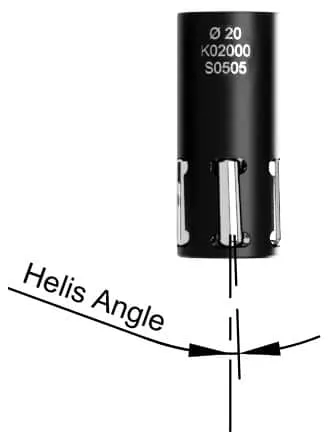
What are self-feeding tools and where are they used?
The self-feeding feature is achieved through the helix angle of the rollers. The tool automatically pulls itself through the bore — you only need to provide rotation. This is ideal for drill presses, column drills and universal lathes. Self-feeding tools can also be used on CNC machines, but the machine feed rate must be higher than the tool's pulling speed.
-
Why do blind hole tools have limited diameter adjustments?
In burnishing tools, diameter adjustment is made by forward/backward movement of the conical shaft. As the tool expands, the risk of the conical shaft tip hitting the bottom of the hole increases. In stepped holes, the shaft can enter the step, allowing more adjustment range.
-
Which parts wear out and can rollers be replaced individually?
The rollers are the primary wear item — they are in constant contact with the surface. Over time, the conical shaft also wears. Rollers are replaced as a complete set, not individually. After several roller set replacements, the conical shaft may need changing. Tool life is significantly longer than conventional cutting tools because burnishing is a non-cutting process.
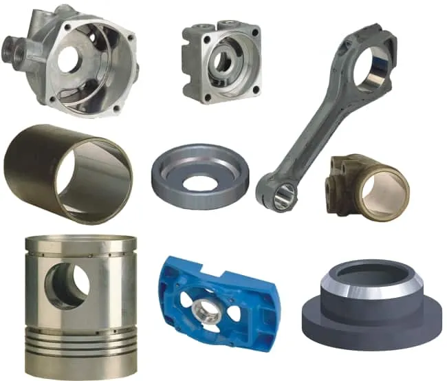
Applications
Application Examples
Internal roller burnishing is used wherever a bore requires a precise diameter, low surface roughness or increased fatigue resistance. Common applications include hydraulic cylinders, pneumatic valve bores, bearing seats, gear bores and injection moulding components. The process replaces honing and internal grinding in many cases — delivering the same or better surface quality in a fraction of the time, with no abrasive waste.
Related Products
Other Burnishing Tools
Need help selecting the right burnishing tool for your application?
Our engineers will recommend the correct tool type, size and parameters for your workpiece geometry and material.
Contact Us