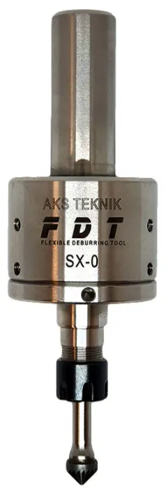
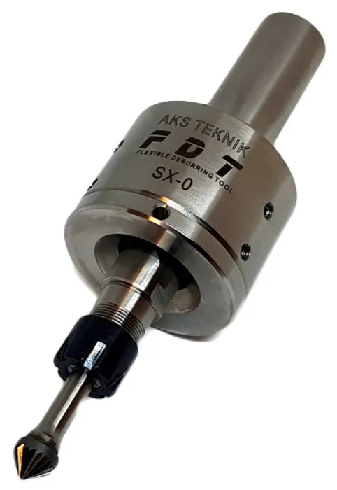
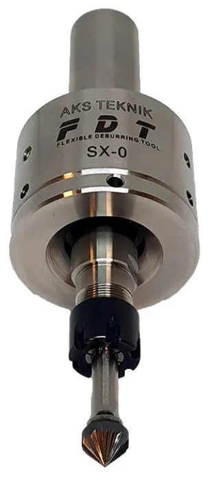
FDT SX0 Flexible Deburring Tool
Spindle-driven flexible deburring tool with reproducible process reliability — automatically follows undefined workpiece edges, no air supply required.
- Spindle-driven — no air supply, no extra infrastructure
- Compensates 5–10 mm undefined edge deviations automatically
- Designed for series production — consistent chamfer batch to batch
- Maintenance free — no pneumatic components, no consumables beyond the cutter
Overview
Spindle-Activated Flexible Deburring for CNC Machining Centres and Lathes
FDT SX0 is a flexible deburring tool designed to automatically remove burrs from CNC-machined parts with undefined or varying edges. Its spring-loaded radial deflection mechanism follows the actual workpiece contour and compensates deviations of 5–10 mm without manual adjustment. Contact pressure is steplessly adjustable via a built-in spring mechanism, and the deflection force remains constant regardless of how much the spindle deflects. The tool is driven directly by the CNC machine spindle — no air supply, no extra infrastructure, no tool change required.
FDT SX0 is designed for series production. Because the flexible mechanism automatically corrects differences between the programmed contour and the actual workpiece, every part in a batch receives the same chamfer width — independently of dimensional or positional variations. This high and reproducible process reliability eliminates the need for manual deburring, reduces operator injury risk, and allows the deburring cycle to run unattended within the existing CNC programme.
Suitable for CNC machining centres, turning centres, and automatic lathes. Particularly effective for contour edge deburring on workpieces with varying or undefined geometry where rigid tools cannot maintain consistent contact. Works on all workpiece materials including steel, aluminium, cast iron, non-ferrous metals, and hardened materials.
Advantages
Key Advantages
- High and reproducible process reliability — spring mechanism is mechanical, not dependent on air pressure or operator skill
- Designed for series production — identical chamfer width on every workpiece, shift after shift
- Steplessly adjustable lateral contact pressure — set exact deburring thickness for each application
- Unchanged deflection force at any spindle deflection angle — consistent edge contact throughout the contour
- Eliminates manual deburring — reduces labour cost and operator injury risk from sharp edges
- Simplified CNC programming — program to nominal contour, tool compensates actual edge deviations automatically
- Maintenance free — no pneumatic components, no air lines, no service intervals
- No chamfer width deviations caused by air pressure variations
- High feeds and speeds: 3,000–8,000 rpm, feed 2,000–4,000 mm/min
- Eliminates tool breaks — flexible mechanism absorbs edge impact instead of transmitting it to the spindle
- Compact design — fits any CNC tool magazine or automatic tool changer
- Extended reach by changing cutter length — access deep cavities and hard-to-reach spots without a tool swap
Specifications
Technical Specifications
| Parameter | Value |
|---|---|
| Order Code | 20.420.00 |
| Activation | Via machine spindle (CNC machining centres, turning centres, automatic lathes) |
| Spindle speed | 3,000 – 8,000 rpm (starting speed 5,000 rpm recommended) |
| Feed rate | 2,000 – 4,000 mm/min (F = 3,000 mm/min recommended; keep constant through direction changes) |
| Max. lateral deflection | 5 mm (10 mm with 100 mm long cutter) |
| Deflection angle | Lateral — 5° |
| Contact pressure | Steplessly adjustable via rear setscrew — tool is shipped pre-set to recommended pressure; increase or decrease as needed |
| Collet | ER-11 — ships with 6 mm collet as standard (accepts ⌀1–7 mm collets; 6.4 mm / ¼" collet available for US customers on request) |
| Shank | 20 mm cylindrical (standard) — collet or hydraulic holder recommended. Weldon flat available on request. Other custom configurations possible as special orders; contact AKS Teknik. |
| Materials | All workpiece materials — steel, stainless steel, aluminium, cast iron, non-ferrous metals, hardened materials |
| Air supply | Not required |
| Maintenance | Completely maintenance free |
| Variant — FDT EHS | Extra Hard Spring variant for setups using extended cutters where standard spring pressure is insufficient. Contact AKS Teknik for details. |
| Custom configurations | ER16 and ER20 collet versions, non-standard shank diameters, and special holder configurations available on request. Contact AKS Teknik for details. |
How to Use
Operating Instructions
- 01
Program the nominal contour
Program the tool path so it presses 1–3 mm into the actual part contour — this lateral offset keeps the cutter permanently pre-tensioned against the edge throughout the cycle. The closer the programmed path follows the real part contour, the more consistent the deburring result. Approach and withdrawal movements should be tangential where the geometry allows.
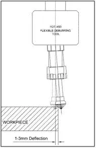
Lateral Deflection of Deburring Tool Spring Deflection in Action - 02
Set cutting direction — clockwise
Program clockwise spindle rotation (climb milling, viewed from above). This is the correct cutting direction for the carbide cutter to deburr effectively without loading the flexible spindle against its travel direction.
Cutting Direction - 03
Set lateral pre-tension and contact pressure
FDT SX0 ships pre-set to the recommended contact pressure via the rear setscrew. If the cutter runs unevenly or jumps, the pressure is too low — increase it via the setscrew. Higher pressure → wider chamfer; lower pressure → narrower chamfer.
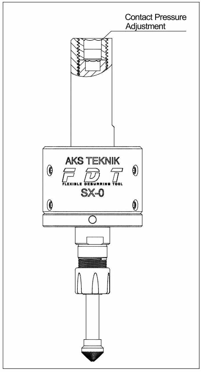
Contact Pressure Adjustment - 04
Set axial cutter position
Position the tool so the deburring edge contacts approximately the middle of the conical cutter. Working closer to the tip reduces the removal rate and produces a narrower chamfer; working further back increases it. Note: deburring thickness depends on axial position and contact pressure — not on the lateral (radius correction) position of the tool.
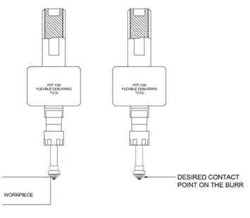
Contact Point of the Burr - 05
Program radius at direction changes
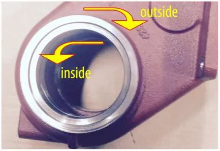
At inside corners, program a small radius instead of a sharp 90° transition. This prevents the cutter from simultaneously contacting two perpendicular surfaces, which causes chatter and uneven deburring. For outside corners, extend the tool path beyond the corner and change direction outside the workpiece.
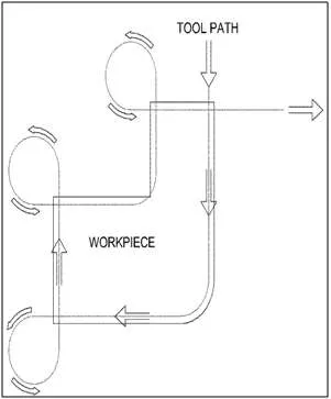
CNC Deburring Tool-Path on Workpiece Contour - 06
Keep feed rate constant through the cycle
Maintain a constant feed rate throughout the deburring cycle, including direction changes. Feed rate variations cause uneven chamfer widths. If deburring is too heavy, increase feed rate or reduce contact pressure. If chamfer is too small, reduce feed rate or increase pressure. Change one parameter at a time and run a test pass after each adjustment.
- 07
Use cooling lubricant for aluminium workpieces
When deburring aluminium, cooling lubricant is required. For all other materials, cooling lubricant is not mandatory but improves deburring quality and surface finish. Apply lubricant through the machine's standard coolant supply.
Cutter Selection
Recommended Deburring Cutters for FDT SX0
FDT SX0 uses an ER-11 collet and accepts carbide deburring cutters with shank diameters from ⌀0.5 mm to ⌀7 mm. The cutter geometry — fine cut or chipbreaker, and point angle — directly affects deburring quality and vibration behaviour on a flexible tool.
| Cutter Type | Characteristics | Use Case |
|---|---|---|
| 90° fine cut conical burr KSK · dia. 10 mm · shank 6 mm · Z3 | Continuous cutting edge, low vibration tendency, clean chamfer | Recommended starting cutter for most applications. Included complimentary with FDT SX0 orders from AKS Teknik. |
| 90° chipbreaker carbide burr | Interrupted cutting edge, higher chip clearance | Suitable for heavy burr removal. Chipbreaker geometry increases vibration tendency on flexible tools — use fine cut geometry if cutter runs unevenly. |
| 60° chipbreaker carbide burr | Narrow point angle, better access to inside radii and deep corners | Use where 90° geometry cannot reach narrow internal features. Same vibration caution applies as 90° chipbreaker. |
If the cutter runs unevenly or tends to jump, increase the lateral contact pressure first. If uneven running continues after pressure adjustment, switch to a fine cut cutter geometry before changing other parameters. AKS Teknik stocks compatible carbide deburring cutters in multiple geometries — contact us for availability.
FAQ
Frequently Asked Questions
-
What is a flexible deburring tool?
A flexible deburring tool is a CNC-compatible cutting tool with a spring-loaded radial deflection mechanism that automatically follows undefined or varying workpiece edges. Unlike rigid tools, it compensates for edge deviations of 5–10 mm without manual adjustment or tool change. The AKS Teknik FDT SX0 is spindle-activated — driven directly by the CNC machine spindle at 3,000–8,000 rpm with no air supply required.
-
How does FDT SX0 work in a CNC machining center?
FDT SX0 has a 20 mm cylindrical shank and is driven by the machine spindle. Collet or hydraulic holders are recommended for best runout and to prevent clamping marks. Custom shank diameters (16 mm, 12 mm) and Weldon flat are available on request — contact AKS Teknik for details. A built-in flexible mechanism allows the ER-11 carbide cutter to deflect laterally up to 5 mm (10 mm with a 100 mm extended cutter), maintaining consistent contact pressure on the workpiece edge. The entire deburring cycle is programmed into the CNC using the nominal workpiece contour — the tool compensates actual edge deviations automatically, so no operator intervention and no separate tool change are required.
-
Does FDT SX0 require a separate compressed air supply?
No. FDT SX0 is spindle-driven and operates without compressed air. This is a key advantage over pneumatic deburring tools, which depend on stable air pressure to maintain consistent chamfer widths. With FDT SX0, deburring quality is independent of workshop air supply variations — making it suitable for unmanned and lights-out machining shifts.
-
What workpiece geometries is FDT SX0 suitable for?
FDT SX0 is particularly effective for contour edge deburring — workpieces with varying or undefined edges where a rigid tool cannot maintain consistent contact along the full contour. The flexible mechanism follows the actual edge automatically, compensating deviations between the programmed and actual contour. Extended cutter lengths allow access to recessed or hard-to-reach areas, and the full tool path is programmable within the existing CNC cycle.
-
What is the difference between FDT SX0 and FDT AXIAL deburring tools?
FDT SX0 deflects radially (laterally, up to 5°), making it ideal for contour edge deburring and profile edges with varying or undefined geometry. The FDT AXIAL series deflects in the axial (Z-axis) direction, which is better suited for flat face deburring, hole entry and exit chamfers, and push/pull applications. Both are spindle-driven, require no tool change, and use ER-11 collets with standard carbide deburring cutters.
-
How do spindle speed, feed rate, and contact pressure affect the deburring result?
Each parameter has a direct and predictable effect on chamfer width and quality. Increasing spindle speed produces a greater deburring effect and smoother finish. Increasing feed rate reduces the deburring effect — lower feed means wider chamfer. Greater lateral contact pressure also increases deburring width. The axial position of the cutter (how far back from the tip it contacts the edge) is the primary control for removal rate — working closer to the tip reduces material removal. Adjust one parameter at a time and run a test pass after each change to isolate the effect clearly.
-
What type of deburring cutter should I use with FDT SX0?
FDT SX0 accepts carbide deburring cutters from ⌀0.5 mm to ⌀7 mm shank diameter via its ER-11 collet. For most applications, a 90° fine cut conical carbide burr — KSK type, dia. 10 mm, shank 6 mm, Z3 universal medium — delivers clean, consistent chamfers with low vibration tendency. This is the cutter AKS Teknik includes complimentary with FDT SX0 orders. Chipbreaker geometry cutters in both 60° and 90° are also compatible and work well on heavier burrs, but chipbreaker geometry increases vibration tendency on flexible tools — fine cut geometry is preferred for most flexible deburring applications. If the cutter runs unevenly or jumps during use, first increase the lateral contact pressure. If uneven running persists, switching to a different cutter geometry is the recommended next step.
-
Can FDT SX0 be used on CNC lathes?
Yes. FDT SX0 is compatible with CNC machining centres, turning centres, and automatic lathes — any machine that accepts a 20 mm shank tool. No additional installations such as compressed air connections or spindle indexing are required. The tool is driven by the machine spindle and the deburring cycle is fully integrated into the existing CNC programme. The standard shank is cylindrical 20 mm — collet or hydraulic holders are recommended for best runout and to prevent clamping marks on the shank. For lathes with live tooling using an ER25 holder, AKS Teknik supplies a special ER25–20 mm collet so the tool fits directly in the live tool turret without any machine modification. Weldon flat shank is available on request.
Applications
Typical Industries & Workpieces
Videos
FDT SX0 in Action
Downloads
Technical Documents
Related Products
Other Deburring Tools
Ready to automate your deburring process?
Our engineers will help you select the right tool for your application and material.
Contact Us