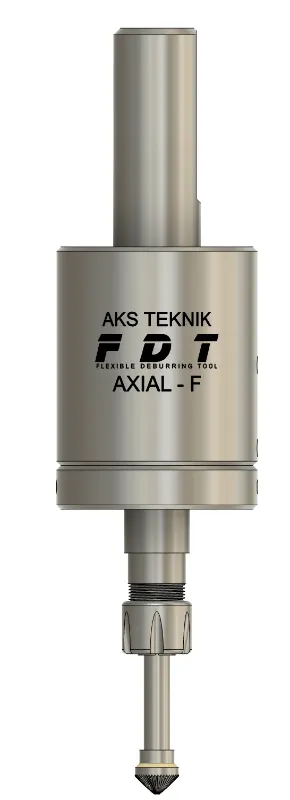
FDT AXIAL (F) Deburring Tool
Axial deflection push-type deburring tool — compensates variable height profiles and curved surfaces automatically, no air supply required.
- Spindle-driven — no air supply, no extra infrastructure
- 10 mm axial push stroke — compensates axial and radial position deviations automatically
- Steplessly adjustable pre-tension force via rear setscrew — repeatable settings
- ER-11 collet — ships with 6 mm collet as standard (accepts ⌀1–7 mm collets; 6.4 mm / ¼" collet available for US customers on request)
Overview
Axial Push-Type Deburring for CNC Machines, Robots and Machining Centres
FDT AXIAL (F) is a simple and economical spindle-driven deburring tool for use on CNC machining centres, NC machines, and industrial robots. By constantly pressuring the cutting edge against the workpiece surface in the axial (Z-axis) direction, FDT AXIAL (F) reliably deburrs the sides and faces of machined parts.
The tool has a push stroke of 10 mm in the axial direction and is particularly effective for deburring profiles with variable height or holes on curved surfaces. Set the Z-axis height by applying a pressure of 1–2 mm from the point farthest from the spindle (the lowest Z coordinate) — FDT AXIAL (F) will automatically compensate for changes in altitude throughout the deburring cycle.
The axial pre-tension force is steplessly adjustable via a rear setscrew — the tool ships pre-set to the recommended pressure and can be increased or decreased as needed. Three spring types (soft, medium, hard) cover the full range of materials, with each spring offering its own stepless adjustment range via the setscrew.
Beyond deburring, FDT AXIAL (F) is suitable for milling protruding material residue on cast workpieces and surface finishing operations using compatible grinding bits — all via the same ER-11 collet interface.
Advantages
Key Advantages
- Simple and economical design — fewer components than pneumatic tools, lower cost per unit
- 10 mm axial push stroke — compensates axial and radial position deviations automatically without reprogramming
- Stepless pre-tension via rear setscrew — adjust contact pressure without spring swap; ships pre-set to recommended pressure
- 3 spring types available — soft, medium, and hard to match material hardness and edge condition
- No air supply required — spindle-driven, no pneumatic infrastructure needed
- Compatible with CNC machines and robots — fits any tool holder accepting a 20 mm cylindrical or Weldon flat shank
- ER-11 collet system — ships with 6 mm collet as standard (accepts ⌀1–7 mm collets; 6.4 mm / ¼" collet available for US customers on request)
- Curved surface capability — compensates height changes on non-planar and inclined workpiece faces
- Cast workpiece compatible — mills protruding material residue in addition to standard edge deburring
- Concordant milling direction — climb milling for clean chamfer finish and reduced cutter wear
Specifications
Technical Specifications
| Parameter | Value |
|---|---|
| Order Code | 21.420.00 |
| Activation | Via machine spindle (CNC machining centres, NC machines, robots) |
| Deflection type | Axial — push (Z-axis direction) |
| Max. axial stroke | 10 mm (push) |
| Spindle speed | 3,000–10,000 rpm |
| Feed rate | 2,000–4,000 mm/min |
| Z-axis offset | 1–2 mm below lowest Z coordinate (farthest point from spindle) |
| Milling direction | Concordant — clockwise spindle rotation |
| Contact pressure | Steplessly adjustable via rear setscrew — tool is shipped pre-set to recommended pressure; increase or decrease as needed |
| Spring options | 3 types — soft / medium / hard; each steplessly adjustable within its own range via setscrew |
| Collet | ER-11 — ships with 6 mm collet as standard (accepts ⌀1–7 mm collets; 6.4 mm / ¼" collet available for US customers on request) |
| Shank | 20 mm cylindrical (standard) — collet or hydraulic holder recommended. Weldon flat available on request. Other custom configurations possible as special orders; contact AKS Teknik. |
| Air supply | Not required |
| Variants & options | Standard tool: ER-11 collet, Ø20 mm shank. ER-16, ER-20 and ER-25 collet versions available on request. Larger-body high-spring-force models manufactured to special order — contact AKS Teknik. |
How to Use
Operating Instructions
- 01
Select the correct spring
Choose between the three available spring types — soft, medium, or hard. The force difference between types is relatively small; the selection is a starting point rather than a strict rule. For aluminium and light alloys, the soft spring is a reasonable starting choice. For steel and cast iron, begin with medium. Switch to hard only if medium does not generate sufficient chamfer. Once the spring is installed, fine-tune contact pressure within its range using the rear setscrew.
- 02
Set the Z-axis offset — 1–2 mm below lowest point
Adjust the height Z axis by applying a pressure of 1–2 mm from the point farthest from the spindle — the lowest Z coordinate on the workpiece surface. The FDT AXIAL (F) will automatically compensate for changes in altitude throughout the deburring path.
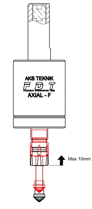
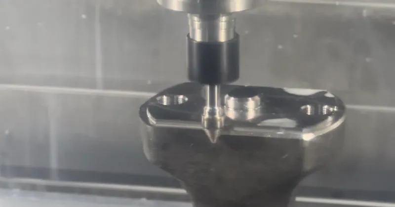
FDT AXIAL (F) Technical Drawing Spring Compression in Action - 03
Set cutting direction — clockwise
Program the spindle to rotate clockwise (M03). FDT AXIAL (F) is designed for concordant (climb) milling — the cutter engages the edge in the direction of feed, producing a clean chamfer with lower cutting forces and reduced cutter wear compared to conventional milling. Reversing the spindle direction is not recommended and will cause premature tool failure.
- 04
Set spindle speed and feed rate
Recommended range: 3,000–10,000 rpm at F2,000–4,000 mm/min. For aluminium, use the upper end of the speed range and apply generous cutting fluid — this produces a clean edge and extends cutter life. For steel and cast iron, start mid-range and adjust based on chamfer result. Keep feed rate constant throughout the cycle; feed variation causes uneven chamfer width. Change one parameter at a time and run a test pass after each adjustment.
- 05
Run a test pass and adjust contact pressure
Run a single deburring pass and inspect the chamfer. If the result is too light (burr remains), increase contact pressure via the rear setscrew — or switch to a stiffer spring. If the cutter leaves marks or the chamfer is too large, reduce pressure. Change one parameter at a time and run a test pass after each adjustment.
Cutter Selection
Recommended Deburring Cutters for FDT AXIAL (F)
FDT AXIAL (F) uses an ER-11 collet and accepts carbide deburring cutters with shank diameters from ⌀0.5 mm to ⌀7 mm — ships with 6 mm collet as standard (6.4 mm / ¼" collet available for US customers on request). The cutter geometry — fine cut or chipbreaker, and point angle — directly affects deburring quality and vibration behaviour on the tool.
| Cutter Type | Characteristics | Use Case |
|---|---|---|
| 90° fine cut conical burr KSK · dia. 10 mm · shank 6 mm · Z3 | Continuous cutting edge, low vibration tendency, clean chamfer | Recommended starting cutter for most applications. Included complimentary with FDT AXIAL (F) orders from AKS Teknik. |
| 90° chipbreaker carbide burr | Interrupted cutting edge, higher chip clearance | Suitable for heavy burr removal. Chipbreaker geometry increases vibration tendency — use fine cut geometry if cutter runs unevenly. |
| 60° chipbreaker carbide burr | Narrow point angle, better access to inside radii and deep corners | Use where 90° geometry cannot reach narrow internal features. Same vibration caution applies as 90° chipbreaker. |
If the cutter runs unevenly or tends to jump, increase contact pressure via the rear setscrew first. If uneven running continues after pressure adjustment, switch to a fine cut cutter geometry before changing other parameters. AKS Teknik stocks compatible carbide deburring cutters in multiple geometries — contact us for availability.
FAQ
Frequently Asked Questions
-
What is the FDT AXIAL (F) and how does it differ from FDT SX0?
Both tools mount in a CNC spindle and use a spring-loaded mechanism to maintain constant cutter contact — but in different directions. FDT SX0 deflects laterally (radially, in the XY plane), making it ideal for contouring along edges where the workpiece geometry is variable or undefined. FDT AXIAL (F) deflects axially (in the Z direction, push type), making it the right choice when the workpiece has height variations along the deburring path — such as holes on inclined surfaces, stepped profiles, or cast parts with uneven faces.
In practice, FDT AXIAL (F) also handles a degree of radial compensation automatically: the conical geometry of the 90° cutter allows the tool to self-centre on the workpiece edge and absorb small XY deviations. This means FDT AXIAL (F) performs well on many of the same applications as FDT SX0 — and is often a more economical alternative where the workpiece geometry does not require full lateral deflection. -
What is axial deflection and when is it the right choice?
Axial deflection means the cutting tool can push back in the Z-axis (up into the spindle) by up to 10 mm against a pre-tensioned spring. When the tool encounters a raised area on the workpiece, the spring compresses and the cutter maintains contact without digging in. This is ideal for: profiles with variable height along the deburring path, holes on curved or inclined surfaces where the entry and exit Z-levels differ, and cast workpieces with uneven parting-line residue. If your workpiece is flat and the variation is in XY geometry (contour shapes), FDT SX0 with lateral deflection is the better choice.
-
How do I set the correct spring pressure for my application?
Use the rear setscrew to adjust the axial pre-tension steplessly — the tool ships pre-set to the recommended pressure, so in many cases no adjustment is needed to get started. If the chamfer is too light, increase pressure via the setscrew; if the tool marks the surface, reduce it. For lighter materials (aluminium, brass), start at a lower pressure and increase until the chamfer is clean. For steel or heavy burrs, increase pressure or switch to the medium or hard spring.
-
Can FDT AXIAL (F) be used on curved surfaces?
Yes. The 10 mm push stroke allows the tool to compensate for height differences along the programmed tool path automatically. Set the Z-axis offset to 1–2 mm below the lowest point (the point farthest from the spindle) on the workpiece surface. As the tool travels over higher regions, the spring compresses and the cutter stays in contact — no additional CNC programming is needed for height compensation.
-
What deburring cutters are compatible with FDT AXIAL (F)?
FDT AXIAL (F) uses an ER-11 collet and ships with a 6 mm collet as standard — the same cutter interface as FDT SX0. It accepts carbide deburring cutters and grinding bits with shank diameters from ⌀1 mm to ⌀7 mm. The recommended starting cutter is the 90° conical carbide burr (fine-cut geometry) — it covers the majority of edge deburring applications. A 6.4 mm (¼") collet is available for US customers on request.
-
Can FDT AXIAL (F) be used on CNC lathes?
Yes. FDT AXIAL (F) is compatible with CNC machining centres, NC machines, turning centres, and robots — any machine that accepts a 20 mm shank tool. No additional installations such as compressed air connections are required. The tool is driven by the machine spindle and the deburring cycle is fully integrated into the existing CNC programme. The standard shank is cylindrical 20 mm — collet or hydraulic holders are recommended for best runout and to prevent clamping marks on the shank. For lathes with live tooling using an ER25 holder, AKS Teknik supplies a special ER25–20 mm collet so the tool fits directly in the live tool turret without any machine modification. Weldon flat shank is available on request.
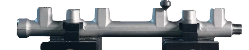
Applications
Typical Industries & Workpieces
Videos
FDT AXIAL (F) in Action
Downloads
Technical Documents
Related Products
Other Deburring Tools
Ready to automate your deburring process?
Our engineers will help you select the right tool for your application and material.
Contact Us