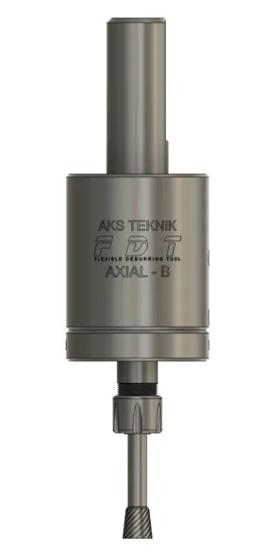
FDT AXIAL (B) Deburring Tool
Pull-type axial deburring tool — deburrs the underside and back face of holes automatically in the CNC cycle. No air supply required.
- Spindle-driven — no air supply, no extra infrastructure
- 10 mm axial pull stroke — deburrs underside and back face of holes automatically
- 3 spring types — select soft, medium or hard to match material and edge condition
- Inverted cone & ball carbide cutters — available on request from AKS Teknik
Overview
Pull-Type Axial Deburring for Underside and Back-Face Applications
FDT AXIAL (B) is a spindle-driven pull-type deburring tool designed to deburr the underside and back face of holes — the exit burr left where a drill, bore, or mill exits the far side of the workpiece. Unlike push-type tools, the spring in FDT AXIAL (B) extends the cutter assembly outward (away from the spindle), enabling the tool to reach behind the workpiece surface and chamfer it in a single CNC cycle pass.
The tool has a pull stroke of 10 mm in the axial direction. To set up, program the Z-axis so the tool tip sits 1–2 mm past the back face of the feature — 1–2 mm beyond the highest Z coordinate (closest point to the spindle). FDT AXIAL (B) will automatically compensate for height variations across the underside surface without additional CNC programming.
Contact pressure is selected via three interchangeable spring types — soft, medium, and hard — to match the workpiece material and edge condition. Choose the appropriate spring for your application; no further adjustment is needed to start deburring.
FDT AXIAL (B) uses an ER-11 collet and is designed for use with inverted cone carbide cutters or ball (spherical) cutters — available from AKS Teknik on request.
Advantages
Key Advantages
- Underside deburring in the CNC cycle — eliminates manual back-face deburring and secondary setups
- 10 mm axial pull stroke — reaches behind workpiece surfaces to deburr exit sides of holes and back-face features
- 3 interchangeable spring types — select soft, medium, or hard to set contact pressure for your material and edge condition
- No air supply required — spindle-driven, no pneumatic infrastructure needed
- Compatible with CNC machines and robots — fits any tool holder accepting a 20 mm cylindrical or Weldon flat shank
- ER-11 collet system — ships with 6 mm collet as standard; accepts inverted cone and ball carbide cutters (⌀1–7 mm shank; 6.4 mm / ¼" collet available for US customers on request)
- Intersecting hole capability — reaches back-side burrs at bore intersections inaccessible from the entry direction
- Concordant milling direction — climb milling for clean chamfer finish and reduced cutter wear on back-face surfaces
Specifications
Technical Specifications
| Parameter | Value |
|---|---|
| Order Code | 22.420.00 |
| Activation | Via machine spindle (CNC machining centres, NC machines, robots) |
| Deflection type | Axial — pull (Z-axis direction, cutter extends outward) |
| Max. axial stroke | 10 mm (pull / extending) |
| Spindle speed | 6,000–8,000 rpm |
| Feed rate | 1,500–3,000 mm/min |
| Z-axis offset | 1–2 mm past highest Z coordinate (point closest to spindle) |
| Milling direction | Concordant — clockwise spindle rotation |
| Contact pressure | 3 interchangeable spring types — soft / medium / hard. Swap spring to adjust pressure level. |
| Collet | ER-11 — ships with 6 mm collet as standard (accepts ⌀1–7 mm collets; 6.4 mm / ¼" collet available for US customers on request) |
| Shank | 20 mm cylindrical (standard). Weldon flat available on request. |
| Air supply | Not required |
| Variants & options | Standard tool: ER-11 collet, Ø20 mm shank. ER-16, ER-20 and ER-25 collet versions available on request. Larger-body high-spring-force models manufactured to special order — contact AKS Teknik. |
How to Use
Operating Instructions
- 01
Select the correct spring
Choose between three spring types — soft, medium, or hard. For aluminium and light alloys, start with the soft spring. For steel and cast iron, begin with medium. Use hard only when medium does not generate sufficient chamfer. Contact pressure is determined by the spring selection — swap the spring to change the pressure level.
- 02
Set the Z-axis offset — 1–2 mm past the back face
Program the Z-axis so the tool tip sits 1–2 mm past the highest Z coordinate on the workpiece — the point closest to the spindle. This means the cutter is positioned slightly beyond the back face of the feature, pre-loading the pull spring. As the tool travels along the underside surface, the spring maintains cutter contact and compensates for height variations automatically.
Spring Extension in Action - 03
Set cutting direction — clockwise
Program the spindle to rotate clockwise (M03). FDT AXIAL (B) is designed for concordant (climb) milling — the cutter engages the back-face edge in the direction of feed, producing a clean chamfer with lower cutting forces and reduced cutter wear. Reversing the spindle direction will cause premature tool failure.
- 04
Set spindle speed and feed rate
Recommended range: 6,000–8,000 rpm at F1,500–3,000 mm/min. For aluminium, use the upper end of the speed range with cutting fluid. For steel, start mid-range and adjust based on chamfer result. Keep feed rate constant throughout the cycle — feed variation causes uneven chamfer width on the back face. Change one parameter at a time and run a test pass after each adjustment.
- 05
Run a test pass and adjust contact pressure
Run a single deburring pass and inspect the back-face chamfer. If the chamfer is insufficient (burr remains on the underside), switch to a stiffer spring. If the cutter marks the surface or the chamfer is too large, switch to a softer spring. Adjust one parameter at a time and run a test pass after each change.
Cutter Selection
Recommended Deburring Cutters for FDT AXIAL (B)
FDT AXIAL (B) uses an ER-11 collet and ships with a 6 mm collet as standard — accepting carbide cutters with shank diameters from ⌀1 mm to ⌀7 mm (6.4 mm / ¼" collet available for US customers on request). The tool is designed for use with inverted cone carbide cutters or ball (spherical) cutters, both available from AKS Teknik on request.
| Cutter Type | Characteristics | Use Case |
|---|---|---|
| Inverted cone carbide burr Shank 6 mm | Narrow at shank end, widens toward cutting face — contacts the back-face edge with the full cutting diameter | Recommended for most underside deburring applications: through-hole exit chamfering, intersecting hole back-edge deburring, flat back-face features. Available from AKS Teknik on request. |
| Ball (spherical) carbide burr Shank 6 mm | Spherical cutting head — self-aligns on curved and angled surfaces | Suited to curved back-face surfaces, profiled underside features, and applications where the back face is not flat. Available from AKS Teknik on request. |
Contact AKS Teknik for cutter availability and recommendations for your specific application.
FAQ
Frequently Asked Questions
-
What is the FDT AXIAL (B) and how does it differ from FDT AXIAL (F)?
Both tools mount in a CNC spindle and use a spring-loaded mechanism for axial compensation — but in opposite directions. FDT AXIAL (F) is a push type: the spring compresses when the cutter contacts the workpiece from above. It is used for deburring the top face or front entry of holes and profiles.
FDT AXIAL (B) is a pull type: the spring extends the cutter assembly outward (away from the spindle). This allows the tool to reach behind the workpiece surface and deburr the underside — the back face or exit side of holes and through features. The tool is programmed to pass slightly beyond the workpiece surface; the extended cutter then contacts and chamfers the back edge automatically as the tool moves. -
What is pull-type axial deflection and when is it the right choice?
Pull-type axial deflection means the cutter assembly is spring-loaded to extend outward — the spring pushes the cutter away from the spindle body rather than resisting compression. The maximum extension stroke is 10 mm.
Use FDT AXIAL (B) when you need to deburr: the exit side of through-holes (the burr left where a drill exits the back face), underside chamfering of bored or milled features, and intersecting holes from the back where the internal intersection leaves a burr on the far side. If you need to deburr the entry or front face of holes and top surfaces, use FDT AXIAL (F) (push type) instead. -
How do I set the Z-axis offset for underside deburring?
Program the Z-axis so the tool tip sits 1–2 mm past the highest Z coordinate on the workpiece — i.e., 1–2 mm beyond the back face of the feature being deburred (the point closest to the spindle). This pre-loads the pull spring. As the tool travels along the back face, the extending spring maintains cutter contact automatically, compensating for height variations without additional Z-axis programming.
-
Can FDT AXIAL (B) deburr intersecting holes from the back?
Yes. FDT AXIAL (B) is specifically suited to deburring the back side of intersecting holes — where one bore crosses another and leaves an internal burr at the intersection that is inaccessible from the entry direction. The pull stroke allows the extended cutter to contact and remove these burrs in a single CNC cycle pass without repositioning the workpiece. The 10 mm stroke provides sufficient reach to compensate for positional variations across different workpiece geometries.
-
What deburring cutters are compatible with FDT AXIAL (B)?
FDT AXIAL (B) uses an ER-11 collet and ships with a 6 mm collet as standard — accepting carbide cutters with shank diameters from ⌀1 mm to ⌀7 mm (6.4 mm / ¼" collet available for US customers on request). The tool is designed for use with inverted cone carbide cutters or ball (spherical) cutters, both available from AKS Teknik on request. The inverted cone geometry is recommended for most underside deburring applications; ball cutters are suited to curved back-face surfaces and profiles.
-
Can FDT AXIAL (B) be used on CNC lathes?
Yes. FDT AXIAL (B) is compatible with CNC machining centres, NC machines, turning centres, and robots — any machine that accepts a 20 mm shank tool. No compressed air supply is required. For lathes with live tooling using an ER25 holder, AKS Teknik supplies a special ER25–20 mm collet so the tool fits directly in the live tool turret without machine modification. Weldon flat shank is available on request.
Applications
Typical Industries & Workpieces
Through-Hole Underside Chamfering
Deburring the exit side of drilled or bored through-holes — the back-face burr left where the tool exits the workpiece. A single FDT AXIAL (B) pass in the CNC cycle eliminates manual deburring of hole exit burrs across the full part in one setup, with no workpiece repositioning required.
Intersecting Holes — Back-Side Deburring
Removing internal burrs at the back side of bore intersections — where one hole crosses another and leaves an internal burr on the far side that is inaccessible from the entry direction. The 10 mm pull stroke provides the reach needed to contact and remove these burrs in a single CNC pass.
Cast Workpiece Back-Face Features
Deburring back-face edges on cast parts, where surface variation and porosity require a compliant tool that maintains contact regardless of local height changes. The pull stroke automatically compensates for casting surface irregularities without CNC programme changes.
Downloads
Technical Documents
Related Products
Other Deburring Tools
Ready to automate your deburring process?
Our engineers will help you select the right tool for your application and material.
Contact Us